close
Choose Your Site
Global
Social Media
Views: 0 Author: Site Editor Publish Time: 2026-11-17 Origin: Site
Drilling deep wells introduces extreme pressure variables. To maintain well control, rig crews rely on specialized containment systems. A Choke Manifold serves as this critical well-control apparatus. It safely lowers wellbore pressure to manage kicks and prevent catastrophic blowouts. When operators lose pressure control, the results are devastating. Rigs face severe non-productive time (NPT), unacceptable safety hazards, and immediate equipment failure. Selecting the right manifold configuration requires a careful balance. You must account for expected well pressures, complex fluid types like H2S, and strict regulatory compliance. Standardizing around API specifications ensures robust performance. However, you must also avoid over-engineering the system to maintain operational efficiency. In this comprehensive guide, we explore how these manifolds function during high-stakes events. You will learn about core components, critical flow paths, and key procurement strategies to safeguard your drilling operations effectively.
Primary Function: Choke manifolds precisely regulate wellbore pressure by directing fluid through restrictive orifices during a kick, allowing safe circulation of heavier mud.
System Integration: They operate in tandem with the blowout preventer (BOP) stack, kill manifold, and mud gas separators to form a complete pressure-containment loop.
Component Selection: Choosing between hydraulic and manual configurations depends on the required response time, personnel safety requirements, and rig capabilities.
Compliance Priority: Procurement evaluations must prioritize API Spec 16C compliance and proper NACE material selection for sour service environments.
Drilling operations face constant pressure shifts. A well kick occurs when formation pressure exceeds hydrostatic pressure. This imbalance forces reservoir fluids into the wellbore. The manifold system immediately steps in to hold back-pressure on the well. It carefully manages this fluid influx before it escalates into a blowout. Operators adjust the choke orifices to restrict outgoing fluid flow. This creates dynamic friction and maintains the bottom-hole pressure slightly above formation pressure. You must sustain this delicate balance continuously. Doing so prevents additional formation fluids from entering the annulus while you prepare heavier kill mud.
Handling a kick involves managing extremely volatile fluids. Gas-cut drilling mud expands rapidly as it travels up the wellbore. The manifold acts as a centralized traffic controller for these dangerous fluids. It routes high-pressure fluids away from the vulnerable rig floor. We follow specific routing protocols to ensure safety. Here is how you typically route these fluids:
Initial Diversion: The blowout preventer (BOP) closes and forces returning fluids into the dedicated choke line.
Pressure Reduction: Fluids pass through the manifold’s restrictive valves, stepping down the intense pressure safely.
Gas Separation: The manifold directs the expanded fluid to the mud gas separator to safely vent combustible gases.
Emergency Flaring: If gas volumes exceed separator capacity, operators bypass the separator and route fluids directly to the flare pit.
Sudden pressure changes cause severe damage below the surface. Controlled pressure drops mitigate hydraulic shock to the fragile formation. If pressure drops too quickly, the wellbore walls can collapse. Conversely, excessive pressure spikes can fracture the rock and cause fluid loss. The manifold ensures a smooth, gradual transition of pressure. Furthermore, this regulation protects upstream BOP equipment. Blowout preventers are rugged, but they are vulnerable to destructive pressure spikes. The manifold absorbs these fluctuations, preserving the integrity of your primary containment barriers.
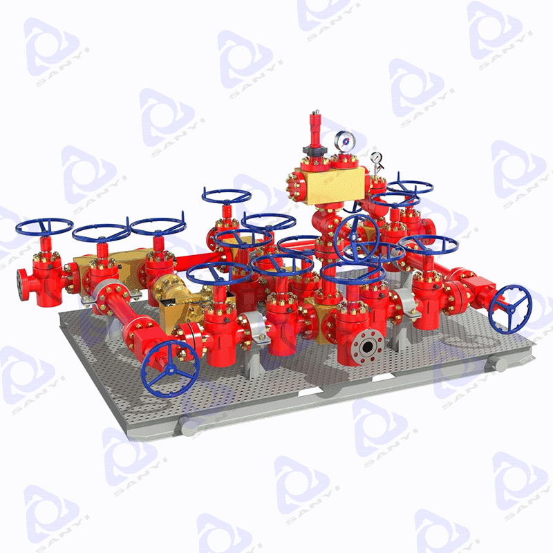
Modern manifolds feature a robust, skid-mounted arrangement. This heavy-duty steel skid provides stability against intense vibrations. Engineers design the layout utilizing an array of valves, high-pressure fittings, and precision pressure gauges. Redundancy forms the foundation of this standard layout. You will find multiple parallel flow paths built into the design. If one side fails or experiences a washout, operators can immediately switch to an alternate path. This dual-path design prevents any interruption during critical well-control events.
Understanding the internal plumbing is vital for quick decision-making. We trace the primary flow path starting from the BOP choke line. High-pressure fluid enters the manifold through a single inlet. From there, the system splits into multiple flow branches. These branches include main choke lines, bypass lines, and dedicated bleed lines. The bypass line handles full-flow circulation when pressure restriction is unnecessary. Bleed lines safely relieve trapped pressure before maintenance. The multiple flow branches ensure continuous operation. Abrasive drilling mud can easily wash out a valve trim. When a washout occurs, you simply close the isolation valves and route flow through a secondary branch.
Component | Location | Primary Function |
|---|---|---|
Gate Valves | Upstream/Downstream of Chokes | Provide full isolation to specific flow paths for maintenance or emergency redirection. |
Choke Valves | Center of Flow Paths | Restrict fluid flow to create specific back-pressure and control kick circulation. |
Pressure Gauges | Inlet and Outlet Headers | Monitor real-time casing pressure and manifold output pressure for accurate adjustments. |
Cross/Tee Fittings | Intersections | Divert flow safely into various branches while withstanding high internal erosion. |
Headers manage the physical dynamics of the fluid. The system utilizes both upstream and downstream headers to stabilize fluid flow. The upstream header receives turbulent, high-pressure fluid directly from the well. It acts as a heavy-duty buffer chamber to distribute this force evenly across the open valves. After the fluid passes the restriction, it enters the downstream header. This component manages the critical transition from high-velocity restricted flow to lower-velocity atmospheric flow. Without these robust buffer chambers, severe pipe vibration would cause structural failure.
Deepwater and complex drilling environments demand rapid responses. A Hydraulic Choke Valve provides unmatched precision during volatile well events. Its primary strength lies in remote operation. Operators control the valve directly from the rig floor or the driller's cabin. This removes personnel from the high-pressure danger zone. It delivers a rapid response to sudden pressure fluctuations. These characteristics make it absolutely essential for high-pressure/high-temperature (HPHT) and ultra-deepwater wells. However, trade-offs exist. These valves require complex hydraulic control panels and dedicated power units. They demand a higher initial CAPEX and enforce rigorous maintenance schedules to prevent hydraulic fluid contamination.
Simplicity often translates to extreme reliability. A Manual Choke Valve operates via a physical handwheel turned by an operator. Its core strengths include reliable mechanical operation and significantly lower upfront costs. Crews find them exceptionally easy to maintain in remote field locations. Due to this reliability, rig designers often use them as a secondary or backup choke on the manifold skid. The primary trade-off involves personnel safety. Operating these valves requires rig workers to stand locally at the manifold. This physical presence introduces severe safety risks during explosive well-control events.
Evaluation Feature | Hydraulic Choke Valve | Manual Choke Valve |
|---|---|---|
Operation Method | Remote (via hydraulic control console) | Local (via manual handwheel) |
Response Speed | Rapid, highly precise adjustments | Slower, relies on operator strength |
Safety Profile | High (personnel kept off manifold floor) | Moderate (requires local presence) |
Maintenance Complexity | High (requires hydraulic line upkeep) | Low (simple mechanical maintenance) |
Rig designers face a balancing act between budget and safety. The industry-standard baseline strongly favors a hybrid approach. A standard skid usually features one hydraulic valve and one manual valve. The hydraulic unit handles primary kick circulation safely from a distance. The manual unit serves as a fail-safe mechanical backup. This hybrid strategy perfectly balances personnel safety, system redundancy, and initial equipment cost. You secure remote capability without overspending on dual hydraulic panels.
Well control requires synchronized input and output. While the choke handles the outgoing pressure, a companion system manages the incoming fluid. A Kill Manifold operates simultaneously alongside the choke side. As the choke regulates outbound casing pressure, the kill side pumps heavy kill-weight fluid directly into the annulus. This heavy mud gradually restores the hydrostatic pressure barrier. You cannot successfully complete the driller's method or the wait-and-weight method without this interoperability. The two manifolds function as a single respiratory system for the wellbore. One exhales the danger, while the other inhales the solution.
Pressure reduction is only the first step in the safety loop. You must also process the volatile fluids safely. The manifold oversees the careful handover of fluid to the mud gas separator, commonly called the poor boy degasser. This downstream vessel receives the expanded, gas-cut mud. Internal baffle plates slow the fluid down further. This allows combustible gases to break out of the mud cleanly. The separator then vents the extracted gas safely up the derrick flare line. Finally, it routes the recovered, gas-free drilling mud back to the active pit system for recirculation.
System integration exposes operations to hidden bottleneck risks. Bottlenecking at the manifold or the downstream separator causes catastrophic back-pressure failures. If the separator cannot handle the volume output from the choke, pressure builds backwards into the manifold. This reverses the flow dynamics and can blow out the liquid seal in the degasser. Proper pipe sizing across all three systems remains a critical engineering requirement. You must ensure the downstream pipe internal diameter is large enough to handle the rapidly expanding gas volume without restricting flow.
Compliance dictates equipment reliability and legal standing. You must rigorously verify that your Original Equipment Manufacturer (OEM) holds valid certifications. API Spec 16C directly governs the design and testing of Choke and Kill Systems. Additionally, API Spec 6A covers the specific requirements for the wellhead and valve components. Operating uncertified equipment invalidates rig insurance and invites severe regulatory penalties. Always request the current, unexpired API certificates before shortlisting any vendor.
Manifolds must survive extreme wellhead conditions. Decision-makers must assess the required working pressure carefully. Ratings typically range from 5,000 psi for standard operations up to 15,000+ psi for deepwater environments. You base this selection strictly on the well's maximum anticipated surface pressure (MASP). Temperature ratings are equally critical. Components must withstand both the high heat of reservoir fluids and the freezing temperatures of rapid gas expansion.
Corrosive environments destroy standard steel rapidly. Hydrogen sulfide (H2S) and carbon dioxide (CO2) pose severe threats to equipment integrity. If operating in these environments, you must require NACE MR0175/ISO 15156 compliant materials. These standards dictate specific metallurgical treatments to prevent sulfide stress cracking. Common API material classes for sour service include EE or FF. Specifying the wrong material class in an H2S environment guarantees catastrophic equipment failure during a kick.
High-velocity mud acts like liquid sandpaper. As operators restrict the choke orifice, fluid velocity increases dramatically. This accelerates erosion on internal components. You must evaluate the internal trim materials closely.
Tungsten Carbide: Ideal for valve stems and seats due to its extreme hardness and resistance to abrasive wear.
Ceramic Linings: Sometimes used in high-wear intersection areas to extend the lifespan of cross and tee fittings.
Reversible Trims: Look for valve designs allowing field crews to flip the internal trim, instantly doubling the component lifespan.
Hardware quality matters, but aftermarket support keeps rigs running. Prioritize suppliers who provide comprehensive, heavily documented data books. You need full material traceability for every pressure-containing part on the skid. If an inspector questions a valve's origin, the data book provides the exact heat treatment records. Furthermore, ensure the OEM offers accessible aftermarket replacement parts. Waiting weeks for a replacement valve trim causes unacceptable NPT. A strong vendor maintains regional stock to minimize your downtime.
Specifying a well-control system represents a high-stakes engineering decision. The manifold you select directly impacts rig safety, environmental protection, and regulatory standing. You cannot afford to treat these systems as interchangeable commodities. Engineering and procurement teams must align the system's pressure ratings, valve configurations, and material classes strictly with their worst-case well scenarios. We strongly advise adopting a hybrid layout to maximize redundancy while protecting rig personnel. Finally, recommend initiating discussions with OEMs early in the planning phase. Provide them with comprehensive well data sheets. This transparency ensures they deliver accurately engineered proposals tailored specifically to your operational hazards.
A: The choke line routes high-pressure fluid out of the wellbore and directs it to the manifold for controlled pressure reduction. Conversely, the kill line is utilized to pump heavy, dense drilling fluid directly into the wellbore. This action restores vital hydrostatic pressure to overcome the formation kick.
A: Routine visual and functional checks occur daily during active drilling operations. Pressure testing to the rated working pressure must strictly adhere to API Standard 53. Crews typically perform these high-pressure tests every 14 to 21 days, or immediately before drilling into a known hazardous transition zone.
A: Yes. Many standard manifolds are engineered with modularity in mind. This allows field crews to replace manual handwheel actuators with hydraulic actuators. However, this upgrade requires purchasing and integrating a corresponding hydraulic control panel and running high-pressure lines to the rig floor.
A: Multiple flow paths provide essential redundancy. High-velocity abrasive fluids can quickly wash out a valve trim during a kick. The parallel branches allow operators to isolate a damaged valve instantly and route flow through a secondary path, ensuring well-control operations remain uninterrupted.