close
Choose Your Site
Global
Social Media
Views: 0 Author: Site Editor Publish Time: 2026-11-13 Origin: Site
Drilling environments demand absolute precision and uncompromising safety protocols. A BOP Control Unit acts as your mission-critical safeguard against unpredictable kicks. It prevents dangerous wellbore pressures from escalating into catastrophic blowouts. Engineers commonly refer to this system as a hydraulic power unit or Koomey unit. It faces a massive mechanical challenge daily. The system must store immense hydraulic energy under severe pressure conditions. It must then deliver this power reliably to actuate heavy ram blocks within seconds.
This comprehensive technical guide provides a detailed walkthrough of these vital systems. We explore core components and stage-by-stage hydraulic actuation sequences. You will learn about strict API compliance calculations and effective failure mode mitigation. Finally, we review essential procurement criteria for drilling engineers and asset managers. Field operators rely heavily on these units during emergencies. Understanding the mechanical synergy between pumps, fluid storage, and control valves is paramount. You can apply these insights to fortify rig safety and maintain operational readiness.
The primary purpose of a BOP control unit is to provide reliable, instantaneous fluid power to seal the wellbore under emergency conditions.
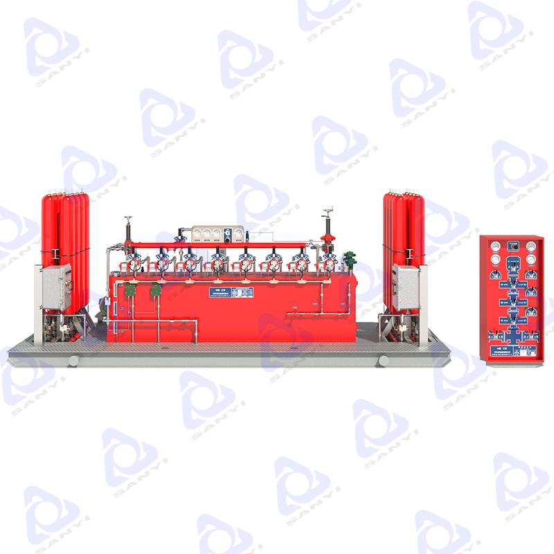
Core systems rely on redundant hydraulic pumps, a high-pressure manifold, and surface accumulator bottles charged with nitrogen.
API Spec 16D governs system sizing, mandating specific closing response times and usable fluid volumes under pressure.
Proactive monitoring of nitrogen pre-charge pressure and hydraulic fluid quality prevents the most common field failures.
Sizing and vendor selection must account for total stack gallonage requirements, environmental extremes, and rig footprint constraints.
Rapid emergency actuation requires instant energy. ASME-coded Accumulator Bottles provide this critical stored power. They function as high-pressure energy reserves. Operators charge them with industrial nitrogen gas. This compressed gas drives the mechanics of fluid separation. The nitrogen acts as a pneumatic spring. It stores non-compressible hydraulic fluid at extreme pressures, typically ranging from 3,000 to 5,000 psi. Both piston and bladder designs exist in the field. Engineers arrange these bottles using a manifold header design. Parallel bank arrangements allow crews to isolate individual bottles. You can perform routine maintenance without initiating a total system shutdown.
Best Practice: Always verify nitrogen pre-charge pressures before commencing drilling operations. Thermal fluctuations heavily influence gas expansion and contraction.
Maintaining optimal system pressure requires robust pump architecture. A triplex electric motor-driven Hydraulic Pump typically serves as the primary pressure generator. It maintains system pressure seamlessly during normal operations. However, rig electrical grids can fail during well control events. Pneumatic or air-operated hydraulic pumps provide an independent secondary backup. The rig's main air supply drives these redundant pumps. They ensure operational continuity during total power outages. Automatic pressure switch controls govern these systems. A standard unit might cut-in at 2,700 psi and cut-out at 3,000 psi. This protects hardware while sustaining constant readiness.
The fluid reservoir supplies the entire hydraulic circuit. Standard engineering rules dictate specific reservoir volume requirements. The tank must hold two to three times the usable accumulator capacity. This ensures adequate fluid remains available during multiple actuation cycles. Quality conditioning components protect the internal machinery. Suction strainers trap large debris. High-pressure filtration assemblies capture microscopic particulates. Fluid sight gauges allow rapid visual inspections. Fluid selection plays a massive role in system longevity. Operators balance water-glycol fluids against specialized mineral oils. You must weigh lubricity, anti-foaming properties, and environmental seal compatibility.
The manifold header directs pressurized fluid to specific rig functions. High-pressure 4-way, 3-position pilot-operated directional control valves manage this flow. They operate in open, neutral, or close positions. Emergency shear scenarios require maximum force. A manual bypass valve function serves this exact purpose. It routes the full 3,000 psi system pressure directly to the ram circuits. This bypasses standard pressure regulation to shear heavy drill pipe. Conversely, annular preventers require delicate handling. Pneumatic or hydraulic regulator valves step down the stored 3,000 psi fluid. They deliver a safe working pressure, typically around 1,500 psi, preventing elastomer damage.
Operators must command the system from secure locations. The master hydraulic control panel sits on a skid near the accumulators. However, the driller needs immediate access. A remote driller's panel sits on the rig floor. Auxiliary toolpusher panels often reside in safe zones. These utilize pneumatic or electro-hydraulic pilot systems. Safety remains the highest priority during stressful events. Panels feature a two-hand interlocking safety design. An operator must simultaneously press a master valve and a function valve. This mechanical safeguard prevents accidental wellhead actuation.
The system spends most of its life in a static standby state. The accumulator bank sits pressurized at its operating setpoint of 3,000 psi. The nitrogen pre-charge rests at a baseline, typically 1,000 psi. The hydraulic pumps remain idle but armed. Continuous system monitoring occurs during this phase. Telemetry systems and mechanical pressure gauges track fluid behavior. They monitor the manifold, annular, and accumulator channels. Operators watch for any slow pressure decay. This decay often indicates a microscopic internal leak.
A well kick demands immediate human intervention. The input action begins when the driller actuates a close function. They might select the pipe rams on the rig floor remote panel. This triggers pilot line signaling. A low-pressure air signal travels swiftly from the remote panel. It moves toward the master control skid. Modern rigs might use an electric signal instead of air. This pilot pressure acts as a shift mechanism. It drives the air cylinder located on the corresponding 4-way valve. The manifold prepares to release stored energy.
The system now translates the signal into fluid movement. Valve positioning changes instantly. The 4-way directional control valve shifts from its center neutral position. It snaps into the close position. Pressure regulation happens simultaneously. Fluid passes through the pressure-reducing and regulating valve. This ensures the pressure stays within the target envelope. Different rams and annulars require different operating pressures. The discharge path opens completely. Pressurized hydraulic fluid channels through armored high-pressure control lines. It races toward the hydraulic chambers located on the blowout preventer.
The fluid arrives at the wellhead with immense kinetic force. Piston displacement occurs rapidly. Pressurized fluid enters the closing chamber of the BOP Stack. This forces the heavy steel ram blocks inward. Alternatively, it squeezes the annular elastomer packing unit tightly around the drill string. Both actions seal the wellbore. Return fluid handling happens concurrently. The moving piston displaces hydraulic fluid from the opening chamber. This fluid travels back up the return conduit. It exhausts directly into the atmospheric reservoir for future recycling.
Actuation consumes stored fluid volume. Pressure drop detection occurs immediately at the skid. Fluid consumption causes the accumulator bank pressure to drop. It quickly falls below the primary cut-in threshold. Pump engagement triggers automatically. Both electric and air-driven hydraulic pumps roar to life. They draw fresh fluid from the reservoir. They force it back into the accumulator bottles against the nitrogen resistance. The pumps run until they restore the bank to its maximum working pressure.
Common Mistake: Ignoring slow pump recharge times. Sluggish recovery often points to clogged suction strainers or failing pump packings.
Engineers must calculate fluid requirements with extreme precision. You must understand the difference between total physical volume and usable fluid volume. Accumulator capacity must significantly exceed the gross actuator volume. Pressure decay curves dictate this reality. As fluid leaves the bottle, the nitrogen gas expands. Expanding gas loses pressure rapidly. We apply the Ideal Gas Law to model this behavior. Rapid emergency discharge creates adiabatic conditions. Heat cannot escape quickly enough. Slow pressure recovery creates isothermal conditions. Sizing equations account for both thermodynamic states to guarantee sufficient power.
The American Petroleum Institute strictly governs system capabilities. API Spec 16D mandates a specific three-function minimum requirement. A compliant unit must hold enough capacity to execute a strict sequence. It must close all ram preventers. It must open the hydraulic choke line valve. Finally, it must close the annular preventer. The system must achieve this without pump assistance. Furthermore, the minimum remaining pressure rule applies. After executing the three functions, the total stored volume must retain pressure. It must sit at least 200 psi above the manufacturer’s minimum specified closing pressure.
Speed prevents blowouts. Regulatory thresholds dictate maximum permissible closing times for surface stacks. Rapid closure mitigates the volume of escaped formation fluids. API standards enforce strict performance metrics.
Table: API 16D Closing Time Thresholds
Equipment Type | Bore Size Specification | Maximum Closing Time |
|---|---|---|
Annular Preventer | Under 18-3/4 inches | Under 30 seconds |
Annular Preventer | 18-3/4 inches and larger | Under 45 seconds |
Ram Preventers (Pipe/Blind) | All sizes | 30 seconds or less |
Ram preventer speed requirements demand full closure on the drill pipe within 30 seconds. Operators conduct periodic draw-down tests to verify these critical response times.
Nitrogen leakage severely cripples fluid delivery. Symptoms manifest clearly during minor function tests. Operators observe rapid pressure drops. Pumps begin cycling on and off excessively during small volume draws. Root causes vary by environment and equipment age. Bladder rupture remains a primary culprit. Charging valve stem leaks also release gas slowly over time. Thermal contraction in sub-zero drilling climates reduces effective pre-charge pressure. Standard operating procedures dictate strict verification methods. You isolate the accumulator bank first. You bleed the hydraulic pressure down to absolute zero. Finally, you take direct mechanical gauge readings at each bottle's gas valve.
Internal leaks compromise system integrity silently. Symptoms include the gradual decay of manifold pressure. You will notice this without finding any external visible leaks. Reservoir fluid levels steadily rise as fluid bypasses the seals. Root causes point to mechanical wear. Erosion degrades the shear-seal surfaces inside directional valves. Abrasive particulates bypass filters and destroy rubber seals. Incorrect packing torque during maintenance also creates leak paths. Diagnostic methods require precision. Mechanics use temperature profiling. They sweep infrared scanners across valve bodies to spot friction heat from fluid movement. Individual return port isolation checks pinpoint the exact failing component.
Hydraulic fluid demands strict contamination control. Common contamination includes moisture condensation from humid rig environments. Drilling mud ingestion occasionally occurs through faulty return lines. Particulate build-up eventually clogs suction strainers. The impact on performance is severe. Starved hydraulic pumps experience violent cavitation. This cavitation causes accelerated mechanical wear on internal pistons. Degraded fluid also results in sluggish valve shift times. Maintenance protocols prevent these issues entirely. Operators perform quarterly fluid sampling. Routine desiccant breather replacement prevents moisture ingress. Filter differential pressure monitoring alerts crews before bypass valves open.
Procurement requires careful alignment with rig geometry. Engineers begin with stack complexity mapping. You must count the total number of preventers. Identify single rams, double rams, shear blind rams, and annulars. Calculate the associated hydraulic gallonage requirements for each component. Operational demands differ wildly between offshore and land rigs. Land rigs prioritize mobility and modularity. Offshore platforms face severe footprint constraints and strict crane lift limits. Hazardous area classifications dictate electrical designs. You must select appropriate enclosures for Class I, Division 1 versus Division 2 or ATEX zones.
System reliability hinges on power availability. Primary power reliability requires careful electrical mapping. You must match the 3-phase electric motor specs to the rig's generator output. Verify correct voltage, frequency, and explosion-proof ratings. Secondary and tertiary air backups require equal scrutiny. Evaluate pneumatic pump compressor volume delivery. Verify the standard cubic feet per minute capabilities under cold-weather operating scenarios. Air lines freeze quickly in sub-zero environments. Emergency manual backup provides the final layer of security. Ensure the availability of high-pressure hand pumps. These allow zero-power survival operations during catastrophic rig blackouts.
Long-term reliability outweighs initial procurement metrics. Operational readiness depends on the rapid availability of API-certified replacement parts. You will eventually need new bladders, check valves, and relief valves. Modern rigs demand advanced interoperability. Evaluate integration with modern digital rig networks. Look for built-in electronic pressure transducers. Automated event logging simplifies audit trails. Alarm telemetry alerts operators to pressure drops instantly. Third-party inspection compliance determines deployment speed. Ensure the unit allows for easy recertification. Adherence to regional safety standards remains non-negotiable. Verify compliance with API 16D, ABS, DNV, or CE directives before finalizing any purchase.
Procurement Checklist:
Map total preventer gallonage against proposed usable volume.
Verify electrical voltage compatibility with rig generators.
Confirm third-party inspection standards for the target drilling region.
Evaluate the local availability of certified elastomer replacement kits.
Understanding a blowout preventer control unit requires grasping complex hydraulic principles. The system relies entirely on the seamless synergy between the accumulator bank, control manifold, and redundant pump systems. These components work together to translate stored energy into massive mechanical force.
The bottom line on well safety remains clear. A control unit's true value lies in predictable, immediate performance. Strict adherence to API sizing standards and rigorous field maintenance guarantee this reliability. As a next operational step, review your existing unit certification records. Implement comprehensive pre-spud draw-down tests before initiating your next drilling campaign. Proactive maintenance always costs less than reactive well control.
A: Conventional surface units typically operate at a 3,000 psi threshold. Deepwater or extreme high-pressure applications may utilize 5,000 psi systems. The manifold uses regulator valves to step this high pressure down. It delivers a safer 1,500 psi operating line specifically for delicate annular preventers.
A: Operators must inspect pre-charge pressures prior to every well spud. During long drilling programs, crews conduct monthly verifications. You must check the pre-charge with zero hydraulic pressure in the system. Always adjust gauge readings against ambient temperature compensation charts for accuracy.
A: API 16D mandates independent power sources to ensure ultimate redundancy. If rig electrical generation fails completely during a blowout, electric pumps become useless. The air-driven pneumatic pumps utilize the rig's stored compressed air. This guarantees uninterrupted hydraulic charging during severe emergencies.
A: Total capacity represents the physical internal space of the bottles. Usable fluid is much smaller. Compressed nitrogen gas occupies half or more of the physical volume. Only a fraction of the remaining space holds hydraulic fluid that can be discharged before pressure falls below critical closing thresholds.